This entry is more or less all about Katydid’s profile – the way that she looks when viewed from the side. There’s lots more to say about her ‘end-on’ view but that will have to wait.
More or less the first thing that I did once Katydid was moved into the shed was to level and measure her. Together with the design offsets provided by Fairlie Restorations from the Fife archive I had enough information to compare Katydid as designed and Katydid as she is now. While the tables of offsets and raw measurements were adequate to confirm a few basic facts I decided to create CAD models of Katydid’s hullform in order to investigate how and to what extent there are differences. The whole process was, for me, amazingly illuminating. I really don’t think that I would have got very far at all in interpreting the history of Katydid’s hull form without the use of CAD. For those of a technical inclination I am using PolyCAD for this work.
Katydid’s sheerline is a bit flat (and bumpy). The weight of the coach roof on the deck structures has nipped her in at the waist and paradoxically, lifted her sheerline amidships, contributing to her rather flat looking sheer. The damage that the running backstays have done to the beamshelf and frames where they attach also indicates that her hullform has been pulled about a fair bit over time. This photo, of Katydid on the water (probably in the 1970’s) gives a general impression of what she most recently looked like afloat.
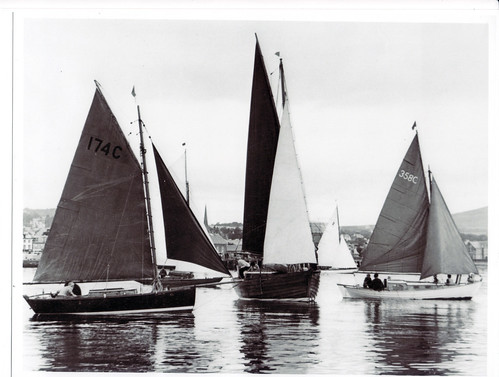
(note that she is a bit fine in the stern and not really designed to carry weight in the cruising cockpit – hence the nose-up attitude)
The datum that I used for measuring Katydid was her scribed waterline. This was (I foolishly thought) a reasonable assumption, particularly since there was no evidence that Katydid had ever been completely re-planked. Once the fact that there were two scribed waterlines on the hull had been sorted out (fortunately they are parallel and either side of the boot top) I dropped a perpendicular from the intersection of the scribed waterline with the front face of her stem (admittedly a bit of a movable feast) and laid out a grid to match the design offsets (11 stations at 1′ 8 1/2″ starting at the DWL/stem interface and waterlines at 6 25/32″ vertical intervals). The idea here was to collect the same measured data as was provided by the design offsets. Once loaded into a model I was presented with a profile that looked as follows.

(Measured lines are green)
The main points to note are
- The measured boat is longer than designed
- The measured forward sheer is lower than designed
- The measured stem and forward keel profile are fuller than designed
- The top face of the measured ballast keel is at a different angle to the designed top of ballast keel
For me, the key point was the last. After a small amount of thought it was clear that the scribed waterline does not coincide with the DWL – either in level or in attitude. So, I rotated the CAD model of the measured boat to align the top face of the ballast keel and re-aligned the front face of the stem with the design model (try doing this on the lofting floor!). This gave me something more useful.

The main (profile) differences remaining are
- The profiles of the ballast keels do not match
- The sheer profile of the measured boat is significantly flatter than the designed boat.
The second point is easily understood when you see the distortion of Katydid’s frames over time and her saggy deck.
Katydid was designed with a lead keel for which we have the displacement calculations but no detailed section data – the keel profile is the only design data available to suggest how it looked. May Kohn confirmed (from reading correspondence in the Scottish Maritime Museum) that the lead keel was removed during the first world war and replaced by a cast iron keel in the 1920’s.
When was the waterline scribed on at the present angle? Why did it not match the DWL? I could speculate that Katydid as built may have sat heavy at the bows but have no proof. Anyway, the fact that we are working with a cast iron keel that needs internal lead ballast to bring her down to her lines, means that we can restore her to float to her design lines.
To complete the hull-form analysis I produced a composite CAD model that included the present backbone structure, current ballast keel and as-designed sections and sheer profile. This defines the shape of the boat that we will restore – being very close to what was lofted in Fairlie in 1891. The main differences relate to getting a good fit between the ballast keel and the lower face of the wooden keel – which has a minor influence on the lower plank lines.

I suspect that we will be looking out for some scrap lead to use as internal ballast. Any offers?
Leave a Reply